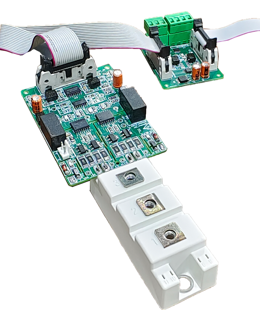
2CHDIG_PRO_485_F10 SiC / IGBT Gate Driver, Differential RS-485, ±15 A
2CHDIG_PRO_485_F10 (VP001559): Isolated Dual-Channel SiC / IGBT Gate Driver, Differential RS-485 Inputs, ±15 A
±15 A peak+15 / –5 V100 kHz5.7 kV isolation test34 mm & 62 mm modulesMade in India by V P Electronics
⬇ Download Datasheet (PDF)Bench Test Procedure (EN)Test Procedure (Hindi)Get Quote
Specifications · Features · Connector · Applications · FAQ · Testing
The 2CHDIG_PRO_485_F10 is a ready-to-mount, two-channel isolated gate driver for half-bridge SiC MOSFET and IGBT modules in 34 mm and 62 mm packages. PWM commands and the fault signal travel as differential (RS-485 style) pairs, giving high noise immunity when the controller and power stage are far apart. On-board isolated DC-DC supplies, DESAT short-circuit protection with soft shutdown, an active Miller clamp and an isolated temperature output make it a complete driver — no separate SMPS needed. Designed and manufactured by V P Electronics, Delhi.
Key specifications
| Configuration | Isolated dual-channel (half-bridge) gate driver, differential inputs |
| Supply voltage | 15 V DC (14.25 V to 15.75 V) |
| Gate drive voltage | +15 V / –5 V |
| Gate peak current | +15 A source / –15 A sink |
| Switching frequency | Up to 100 kHz (driving power depends on frequency) |
| PWM interface | 5 V differential pairs, 120 Ω terminated; 3.3 V to 5 V logic |
| DC bus / working isolation | Up to 2100 V DC |
| Isolation test voltage | 5.7 kV, 50 Hz, 60 s (primary–secondary and secondary–secondary) |
| CMTI | ≥ 100 kV/µs (VCM = 1500 V) |
| Propagation delay (on / off) | 125 ns / 120 ns typ. |
| Short-circuit protection | VCE (DESAT) monitoring, 9.2 V threshold, 200 ns response, 400 mA soft turn-off |
| Miller clamp | 4 A internal active clamp |
| Dead band | Settable: 1 / 3 / 6 / 7 µs (C2 = C3 = 47 / 100 / 220 / 330 pF); interlock when both PWM high |
| Outputs to controller | Differential fault (active low), isolated temperature (RTD) 0.6–1.6 V for 25–135 °C |
| Connector | 16-pin input connector |
| PCB size / mounting | 87 × 67 mm, 4-layer; mounting holes 53.5 × 28.5 mm, Ø 2 mm; direct on module |
| Operating temperature | –40 °C to +105 °C |
Source: V P Electronics preliminary datasheet 2CHDIG_PRO_485_F10 (VP001559), Rev P1, Oct 2026. Specifications subject to change; verify in the final application, including short-circuit timing against the module maker's limits.
Features
- Differential PWM inputs (120 Ω terminated) and differential fault output for long, noisy cable runs
- On-board 2 W isolated power supplies (2 × 1 W driver outputs)
- DESAT short-circuit protection, 200 ns response, 400 mA soft turn-off
- 4 A active Miller clamp; primary over-voltage, reverse-polarity and primary/secondary UVLO protection
- Settable dead band and interlock; enable input; auto or external reset
- Isolated analog sensing: NTC / PTC / thermal-diode temperature or DC-bus voltage
- User-selectable gate resistors (Rg-on / Rg-off, 1.5–10 Ω) and blanking time — works with any make of module
- Green / red LEDs for supply status and fault
16-pin input connector
| Pin | Signal | Function |
|---|---|---|
| 1 | VDC | +15 V supply |
| 2, 12, 14, 16 | Common | Common |
| 3 / 4 | HS_P_PWM / HS_N_PWM | High-side PWM, differential |
| 5 / 6 | LS_P_PWM / LS_N_PWM | Low-side PWM, differential |
| 7 / 8 | FAULT-P / FAULT-N | Fault, differential; low = DESAT or supply fault |
| 9 / 10 | RTD_P / RTD_N | Isolated temperature output |
| 11 | NC | Do not connect |
| 13 | PWM-EN | Low = PWM disabled; open/high = enabled |
| 15 | Reset | High (5 V) clears fault in external-reset mode |
Typical applications
- Motor drives and VFDs
- EV chargers and battery chargers
- DC-DC converters and inverters, UPS and solar inverters
- Medical X-ray and other high-voltage power stages
- University and R&D SiC inverter stacks
Selection tips
- Suits common SiC MOSFET modules up to about 400 A / 1700 V; driving power rises with switching frequency.
- Send the module part number, DC bus, current and frequency — we recommend gate resistors, blanking time and dead band.
- Use twisted-pair cable for the differential PWM and fault lines and keep the 15 V supply within 14.25–15.75 V.
FAQ
Can it drive IGBT modules as well as SiC MOSFETs?
Yes. It is designed for half-bridge SiC MOSFET and IGBT modules in 34 mm and 62 mm packages; gate resistors and blanking time are set to suit the module.
Why differential (RS-485 type) inputs?
Differential pairs reject common-mode noise, so PWM and fault signals stay clean over long cables in high-power, high-dv/dt equipment.
Do I need a separate isolated power supply?
No. Isolated DC-DC converters are on the board; only a 15 V DC supply is needed.
Testing
Check the driver on the bench before mounting, using our step-by-step test procedure: English · Hindi.
Related VP products
IGBT / SiC gate drivers (normal PWM version 2CHDIG_PRO_C10, VP003366), IGBT and SiC modules, heat sinks, DC-link capacitors and complete inverter stacks from V P Electronics.
Designed and made by V P Electronics, Delhi.
Email: sales@vpelectronics.in. Phone: +91-8851410806