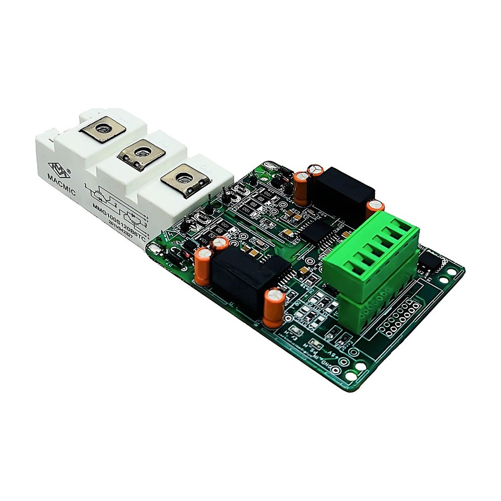
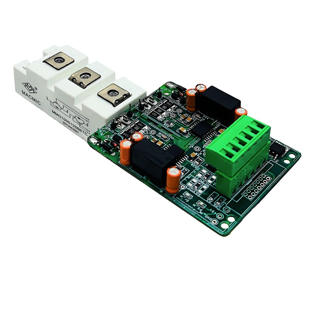
2CHDIG_PRO_C10 IGBT Gate Driver
2CHDIG_PRO_C10 (VP003366): Isolated Dual-Channel IGBT Gate Driver, ±10 A, +15 / –9 V
±10 A peak+15 / –9 VUp to 50 kHz3.3–15 V logicOn-board isolated DC-DCMade in India by V P Electronics
⬇ Download Datasheet (PDF)Gate Current Application NoteBench Test Procedure (EN)Test Procedure (Hindi)Get Quote
Specifications · Gate resistor · Connector · Applications · FAQ
The 2CHDIG_PRO_C10 is a ready-to-mount, two-channel isolated gate driver that mounts directly on half-bridge IGBT modules. An on-board isolated DC-DC converter removes the need for a separate SMPS, the 3.3–15 V logic input connects to any controller, and DESAT short-circuit protection with soft turn-off, a 4 A active Miller clamp and a common error output protect the power stage. Field-configurable blocking time, user-selectable Rg-on / Rg-off and dead band let it drive any make of IGBT module. Designed and manufactured by V P Electronics, Delhi.
Key specifications
| Configuration | Isolated dual-channel (half-bridge) IGBT gate driver, single-ended PWM inputs |
| Supply voltage | 15 V typ. (14.25 V min, 16.5 V max), ~100 mA with load |
| Gate drive voltage | +15 V (14.5–15.5 V) / –7 to –9 V |
| Gate peak current | ±10 A |
| Output power | 2 × 2.4 W at 105 °C |
| Switching frequency | Up to 50 kHz (driving power depends on frequency) |
| PWM interface | 3.3 V to 15 V logic, Schmitt-trigger input |
| Turn-on / turn-off delay | 185 ns / 185 ns |
| Short-circuit protection | VCE (DESAT) monitoring, 9.2 V threshold, response 1.0–4.4 µs (user selectable), soft turn-off |
| Miller clamp | 4 A internal active clamp |
| Dead band | Selectable 1.4–13.2 µs (C2 = C3 = 10–470 pF); interlock when both PWM high |
| Error output | Open collector, 5 V = normal, 0 V = fault; can be paralleled |
| Isolation | DC-DC 5000 VAC (1 min); gate IC working voltage 1500 VRMS / 2121 VDC; CMTI 150 V/ns min |
| Input connector | 6-pin, 5.08 mm pitch |
| PCB / mounting | 87 mm wide board, holes 77 × 47 mm (Ø 4.2 mm); direct on IGBT module |
| Operating temperature | –40 °C to +105 °C |
| Weight | 0.3 kg |
Source: V P Electronics technical datasheet DUAL IGBT DRIVER (±10 A), VP003350 / VP003366 / VP003383, Rev 1.1 (draft), Nov 2026. Specifications subject to change.
Gate resistor and gate charge selection
| External Rg | Peak source | Peak sink |
|---|---|---|
| 1.5 Ω | 10 A | 10 A |
| 2.2 Ω | 8.6 A | 9.6 A |
| 3.3 Ω | 6.2 A | 6.7 A |
| 4.7 Ω | 4.5 A | 4.8 A |
| 6.8 Ω | 3.2 A | 3.4 A |
| 10 Ω | 2.3 A | 2.3 A |
| Switching frequency | Max. module Qg (70 mA design limit) |
|---|---|
| 5 kHz | 14 µC |
| 10 kHz | 7.0 µC |
| 20 kHz | 3.5 µC |
| 30 kHz | 2.33 µC |
| 50 kHz | 1.4 µC |
Driving capability: usual IGBT modules up to 1200 A / 1700 V at 10 kHz. Details in the gate current application note.
Features
- On-board isolated DC-DC converter, 2 × 2.4 W output
- DESAT short-circuit protection with soft turn-off; user-selectable blocking time
- 4 A internal active Miller clamp
- Primary / secondary under-voltage monitoring; supply short-circuit and reverse-polarity protection
- Interlock when both PWM inputs are high; selectable dead band
- Open-collector error output — several drivers can share one controller input
6-pin input connector (5.08 mm)
| Pin | Signal |
|---|---|
| 1 | +15 V |
| 2, 5 | GND |
| 3 | PWM_L |
| 4 | PWM_H |
| 6 | ERROR |
Variants: VP003350 (2CHDIG_PRO_F10, 16-pin FRC input); VP003383 (as VP003366 with input pull-up to +15 V); VP001559 (2CHDIG_PRO_485_F10, differential RS-485 inputs, ±15 A).
Typical applications
- Motor drives and VFDs
- Converters and inverters, UPS and solar inverters
- Induction heating and ballast
- Medical X-ray power stages
FAQ
Which IGBT modules can it drive?
Usual half-bridge IGBT modules up to 1200 A / 1700 V at 10 kHz. Check module gate charge against the Qg table, or send us the module part number.
Do I need a separate isolated supply?
No. The isolated DC-DC converter is on the board; only 15 V DC is needed.
Can it work with 3.3 V or 5 V controllers?
Yes. The PWM input accepts 3.3 V to 15 V logic.
Testing
Check the driver on the bench before mounting, using our step-by-step test procedure: English · Hindi.
Designed and made by V P Electronics, Delhi.
Email: sales@vpelectronics.in. Phone: +91-8851410806