2CHDIG_PRO_C10 IGBT Gate Driver
2CHDIG_PRO_C10 (VP003366): Isolated Dual-Channel IGBT Gate Driver, 10 A Class
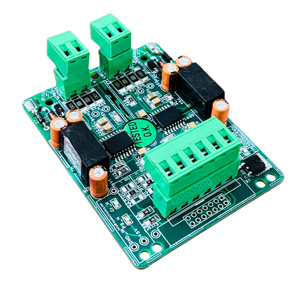
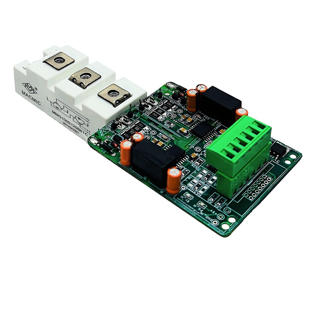
The 2CHDIG_PRO_C10 is a ready-to-use two-channel gate driver for half-bridge IGBT modules. Each channel has its own reinforced-isolated TI UCC21750 driver IC and its own isolated DC-DC converter, so the whole board runs from a single 15 V supply. It mounts directly on the IGBT module and takes 3.3 V or 5 V PWM signals from any controller. The control input is a 6-pin 5.08 mm terminal.
This is a preliminary datasheet (Rev P1, Sep 2026). Specifications are subject to change without notice.
Key specifications
| Parameter | Value |
|---|---|
| Supply voltage | 15 V DC (14.25 V to 16.5 V) |
| Gate drive voltage | +15 V / -9 V (nominal, per channel) |
| Peak gate current | ±10 A (driver IC rating) |
| Gate drive power per channel | 2.4 W (100 mA average per rail) |
| Switching frequency | Up to 50 kHz, depends on IGBT gate charge (see selection table below) |
| Isolation | Driver IC 5.7 kVRMS (UL 1577); DC-DC 5 kVAC (1 min) |
| Operating temperature | -40 °C to +105 °C |
| External gate resistance | 1.5 Ω to 10 Ω |
| PWM inputs | PWM_H, PWM_L, 3.3 V to 5 V logic, active high |
| Propagation delay, on / off | 90 ns typ, 130 ns max (driver IC) |
| Fault output | Common open-collector ERROR, active low |
Features
- Two isolated channels (high side and low side), each with a TI UCC21750 driver: ±10 A peak source and sink current, separate turn-on and turn-off outputs.
- On-board isolated DC-DC converter per channel, +15 V / -9 V, so no separate SMPS is needed.
- VCE (DESAT) short-circuit protection with field-configurable blanking time.
- 400 mA soft turn-off on short circuit, and 4 A internal active Miller clamp.
- Primary and secondary under-voltage lockout.
- Interlock: if both PWM inputs are high, both outputs turn off.
- Selectable dead band, and user-selectable RgON and RgOFF.
- Reverse polarity and short-circuit protection on the 15 V input.
- Direct mounting on the IGBT module, 4-layer PCB.
Why engineers use it
- Single 15 V supply: the isolated gate supplies are on the board.
- Direct controller interface for 3.3 V to 5 V logic.
- One fault line: short-circuit and supply faults share a common ERROR signal.
- Works with any make of IGBT: gate resistors, blanking time and dead band are field-configurable.
Alternative to SKYPER 32 R / SKYPER 32 PRO R and Power Integrations drivers
The 2CHDIG_PRO_C10 can be used in place of Semikron Danfoss SKYPER 32 R and SKYPER 32 PRO R based drivers and Power Integrations IGBT drivers, as a cost-effective alternative with full technical support from V P Electronics.
It is not a pin-to-pin replacement. Send us your present driver model, IGBT module part number, DC bus voltage, current and switching frequency. Our team checks your application against this driver's ratings (±10 A peak gate current, 2.4 W per channel, up to 50 kHz) and supports you with wiring, gate resistor, blanking time and dead band settings.
SKYPER is a trademark of Semikron Danfoss. Power Integrations is a trademark of Power Integrations, Inc. These names are used only to identify the drivers this product can be used in place of.
Applications
Online UPS and inverters, solar inverters, industrial motor drives, converters, rectifiers and battery chargers, induction heating, ballast and medical X-ray.
Protection details
| Function | Description | Value |
|---|---|---|
| Short circuit (DESAT) | VCE is monitored after the blanking time; the driver turns the IGBT off and reports ERROR | Threshold 9.15 V typ at DESAT pin |
| Blanking time | Set by blanking capacitor, configurable for the IGBT used | ≈1 µs (56 pF) to ≈4 µs (220 pF) |
| Soft turn-off | Controlled gate discharge on short circuit, limits VCE overshoot | 400 mA typ |
| Active Miller clamp | Holds gate low in off-state, prevents false turn-on | 4 A |
| Under-voltage lockout | Secondary side on 12.0 V / off 10.7 V typ; primary side also monitored | Auto recovery |
| DESAT to ERROR delay | Driver IC timing | 580 ns typ, 750 ns max |
IGBT selection: gate charge versus frequency
| Switching frequency | Max. IGBT gate charge Qg (µC) |
|---|---|
| 5 kHz | 14.8 |
| 10 kHz | 7.4 |
| 20 kHz | 3.7 |
| 30 kHz | 2.5 |
| 40 kHz | 1.9 |
| 50 kHz | 1.5 |
Qg is over the -9 V to +15 V gate swing, with 20 % design margin. Gate power per channel P = Qg × 24 V × fsw. Example: a module with Qg = 3 µC can run up to about 20 kHz.
Below 3.3 Ω gate resistance at high frequency and high ambient temperature, contact V P Electronics for thermal derating.
Dead band selection (C2 = C3)
| C2 = C3 (pF) | Dead band (µs) |
|---|---|
| 10 | 1.4 |
| 22 | 1.6 |
| 33 | 1.8 |
| 68 | 2.0 |
| 100 | 2.3 |
| 220 | 6.0 |
| 330 | 7.2 |
| 470 | 13.2 |
Connections
CON2, control input, 6-pin 5.08 mm:
| Pin | Signal | Description |
|---|---|---|
| 1 | +15 V | Supply input |
| 2 | GND | Supply / signal return |
| 3 | PWM_L | Low-side PWM input |
| 4 | PWM_H | High-side PWM input |
| 5 | GND | Supply / signal return |
| 6 | ERROR | Fault output, active low |
Gate connections: one 2-pin terminal per channel for Gate and Emitter (Kelvin emitter where available). Keep gate leads twisted and as short as possible.
LED indication: green (PS-H / PS-L) shows channel supply status; red (Error) shows a short-circuit or IGBT fault.
Mechanical and ordering
| Parameter | Value |
|---|---|
| PCB size | 87 × 67 mm, 4-layer |
| Mounting holes | 57 × 47 mm pitch, Ø 4.2 mm |
| Mounting | Direct on IGBT module, open frame |
| Model | VP code | Control input |
|---|---|---|
| 2CHDIG_PRO_C10 | VP003366 | 6-pin 5.08 mm terminal |
| 2CHDIG_PRO_F10 | VP003283 | 16-pin FRC connector |
Selection support
Gate resistance, blanking time and dead band depend on the IGBT module and the application. Send us the IGBT part number, DC bus voltage, current and switching frequency, and we will recommend the settings for your application.
Download Datasheet (PDF) Get Quote
Email: sales@vpelectronics.in. Phone: +91-8851410806
Preliminary datasheet. Values marked "driver IC" are component ratings. The user is responsible for verifying the driver in the final application, including short-circuit protection timing against the IGBT manufacturer's limits.
Related products
Bench test before fitting to the IGBT
Test the driver on the bench, without high voltage, and fit it to an IGBT only after it passes.
Equipment: 15 V DC supply with current meter (limit 0.5 A), PWM generator, 2-channel CRO, multimeter, 2 jumper wires.
Safety: Never connect the DC bus (high voltage) during this test. Connect the CRO ground to the emitter of the same channel (E5 or E7); the high and low sides are isolated. If any part heats, smokes or smells, switch off at once.
| Channel | Bench test: DESAT to | After fitting: DESAT to |
|---|---|---|
| High side | E5 (high-side emitter) | Upper IGBT collector (DC+) |
| Low side | E7 (low-side emitter) | Lower IGBT collector |
LEDs on each side: red = DESAT fault (short circuit in that side's IGBT); green = output-side power-supply fault. In normal condition both LEDs are off.
- Short DESAT first. Connect DESAT-H to E5 and DESAT-L to E7 with jumpers. An open DESAT is seen as a fault: ERROR goes low and no PWM reaches the gate.
- Apply 15 V only, PWM off. Give +15 V on pin 1 and GND on pins 2 and 5. Note the supply current. After 1 to 2 minutes, check that the DC-DC modules, driver ICs and regulator are not hot. LEDs must be off and ERROR (pin 6) must be 5 V high.
- Output rails. On each side, measure +15 V and -9 V with respect to the emitter.
- PWM inputs. Apply PWM to PWM_H (pin 4) and PWM_L (pin 3) at your controller's logic level (3.3 V to 5 V, as in the datasheet). Check the frequency and duty of each pin on the CRO.
- Gate outputs. Measure high-side gate to E5, then low-side gate to E7. Expect +15 V / -9 V PWM with the same frequency and duty as the input. The supply must not heat; note the current.
- ERROR and LEDs. ERROR must be 5 V high and all LEDs off.
After the test (mandatory): Switch off the supply and remove both DESAT jumpers. With a jumper in place, short-circuit protection will not work. Connect high-side DESAT to the upper IGBT collector (DC+) and low-side DESAT to the lower IGBT collector. Connect gate and emitter to the same side's IGBT gate and emitter (Kelvin emitter if available), with short, twisted wires. Run first at low DC bus voltage, then at full voltage.